XaiJu
The100

The100

patreon


The100 posts

T250 Launch Incoming

Hey everyone,

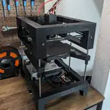
Over the past three weeks, I took some time off—not just to relax, but to prepare. Prepare for what’s ahead. Because the T250 is finally ready to be shown to the world.

The design has been built and tested by over ten Alpha testers, and their feedback made its way back into the printer. THEOS got a major polish too—many of the early quirks have been ironed out, and I was able to squeeze in all the features I had planned. Even the slicer profiles have matured to a point where most prints work straight out of the box with little to no parameter tweaking.

Now it’s time to press the big red launch button and see what the world thinks of the T250.

But before that happens—there’s still a mountain of work ahead:

  • Producing a release video that walks through the features and shows off some fast prints

  • Creating a proper product brochure that explains what the printer is all about at a glance

  • Taking clean, high-res product photos

  • Preparing marketing material for press and influencers

  • Breaking down the design into printable STLs and uploading it to Printables

  • ...and about 100 other things I’ll probably remember in the middle of the night

As always, I’ll keep you posted 2–3 times a week with updates on what I’m working on and where we are in the process. This part of the journey is always exciting and... honestly, a bit boring for me. I’d rather be tinkering with printers than writing about them or filming them.

But I am excited to see how the world reacts to the T250. I hope we’ll welcome a wave of new faces into the community—and leave a few jaws on the floor along the way. And I’ll be even more excited once I can get back to building, because my backlog is packed with wild ideas waiting for their turn.

Thank you so much for your continued support. None of this would be possible without you. Thank you for helping me turn projects like the T250 into reality.

View Post

Updates from the Software Front!

Over the past week, I've mainly been focused on making improvements to Klipper. I absolutely fell in love with the real-time bed-level scanning that the BDSensor provides. Seriously, when it works, it's incredible! It nails the tolerances so perfectly that the first layer sticks flawlessly, even without any adhesive—yes, even at full-blown BSO speeds! Honestly, this is the first printer I've had that pulls this off so effortlessly.

But, of course, nothing's ever perfect. There are definitely a few annoying caveats. Here's a photo my Buildplate I used for the last months tuning my T250:

I've unintentionally carved away parts of the top texture layer. This only ruined the printing surface but also the nozzles I used for carving :-)

The issue occurs because the sensor is mounted 26 mm behind the nozzle along the Y-axis. So, when the toolhead moves close to the maximum Y position, the nozzle itself is still over the print bed—but the sensor is no longer above the printing surface. Without anything underneath it, the sensor reads its maximum offset value (typically -4 mm), which causes Klipper to incorrectly compensate the Z-height. As a result, the nozzle crashes into the bed.

Klipper’s architecture was never really designed with real-time Z-leveling in mind, which makes implementing a proper failsafe pretty tricky. There’s currently no clean or reliable way to handle this natively. So, I started building a few prototypes to see what approach might work best—but honestly, none of them were truly satisfying.

My first attempt was based on the assumption that the Z-delta between two consecutive points during z compensation is usually very small—something in the range of 0.005 mm to 0.01 mm. Based on that, I added a failcheck routine directly into the BD Sensor firmware. The code basically checks if the current measurement deviates too much from the expected average delta, and if it does, it disables Z-adjustment for that spot. It actually worked and solved the carving issue—but I wasn’t thrilled about having to modify the BD Sensor firmware, since that code is maintained by someone else.

I reached out to Markniu and shared the concept with him—good news is, he liked the idea and is now working on an official firmware update that includes this failcheck.

While that’s in progress, I started working on a second approach. The idea here is to define a “safe zone” for Z-adjustments. Since I know all the key parameters—the bed size, the toolhead dimensions, and the offset between the nozzle and the sensor—I can calculate whether the sensor is still actually over the print surface before applying any adjustment.

The real issue here is that the ToolheadMove function is packed with hardcoded exceptions for edge cases that aren't documented anywhere. That makes it really risky to touch. Any changes I make could easily break something I wasn’t even aware could happen. It’s basically spaghetti code at this point, and I’ve got a bad feeling about releasing any modifications I made there—because chances are high they’ll cause unintended side effects that I can’t predict.

So I’ve decided to put that task on hold for now and wait until there’s an official BD Sensor firmware with proper real-time Z-measurement support. On my own machine, I know exactly when the issue can happen—and honestly, my build plate is already scratched, so there’s nothing left to lose. But for the official T250 configuration, I’m disabling real-time adjustment for the time being to avoid any potential damage or confusion.

View Post

Small Details matter....

Over the past week, I focused on enhancing the resolution and quality of fine details in certain prints. Printing Minatures on an FDM Printer is hard. You're facing issues like:

  • Cooling: Precise cooling is crucial to quickly solidify each extruded layer, preventing deformation.

  • Pressure Control: Maintaining consistent pressure inside the hotend is essential to avoid issues such as underextrusion or overextrusion.

  • Gantry Stability: The gantry must exhibit high rigidity to prevent flexing, especially noticeable when printing very small details like a 1x1 mm dot.

Now Imagine you do this x8 faster that you should ;-)

To thoroughly investigate these factors, I printed over 20 different test models during the last week. Throughout these experiments, I varied print temperatures, adjusted printing speeds, and conducted comparative prints using my Voron 350 to benchmark against a standard high-performance printer.

The attached video showcases a worst-case scenario print executed at maximum speed. Observations include noticeable stringing and a rough surface finish on finer details. This particular print utilized a 0.6 mm nozzle, which is typically not ideal for highly detailed miniature models. However, given that all my current print profiles are optimized for a 0.6 mm nozzle, I have decided against initiating a separate tuning project for a smaller, 0.25 mm nozzle at this time.

Below is another smaller-scale print that clearly replicates these same issues, though with reduced filament usage:

These tests were performed using my current quality-speed profile, which has proven highly effective for the majority of my prints. Out of more than 60 different models printed, only three exhibited quality issues significant enough to fall below my established quality threshold.

 Now Im debating with myself to stop here with my miniature tests since the level of detail on normal prints is fantastic and those who are into miniatures would normally use smaller nozzles or a resin printer.

What's your opinion? Let me know in the comments!

View Post

Adaptive Z-Offset Measurement

Hey everyone! Sorry things have been a bit quiet from my side this past week. I was still recovering from COVID, and trust me—running a loud CPAP printer right next to you with a pounding headache isn't fun.

So I was focusing on some enhancements to the THEOS firmware. Over the past few weeks, I've noticed that the BD sensor occasionally produces false-positive readings during the second homing cycle. Although these errors seemed sporadic, there was actually a consistent pattern whenever they occurred. After some digging, I suspected the issue might stem from an incompatibility between my modified second homing routine and the sensor's internal workflow.

I reached out to Markniu, and together we identified the root cause. The solution involves making some architectural changes to how homing is handled overall. It’s a bit more development effort, but the payoff will be huge—we'll be able to measure Z-distance in real-time.

In the video attached, you can see a quick-and-dirty implementation of Adaptive Z-Offset. The results were pretty impressive: out of 10 test patterns, 7 had absolutely perfect first layers. The remaining 3 had minor scratches on the underside, each smaller than a 1x1 cm patch—annoying, sure, but definitely not a dealbreaker.

This week, I'll be focusing on implementing the necessary changes for the Z-Offset feature. Additionally, there have been several bug reports on Discord and here on Patreon. I'll reproduce and address these issues, aiming to roll out a fresh update by the end of the week.

View Post

Printing and Printing and Printing....

Last week was Carnival in my hometown, so productivity took a bit of a hit—too much celebrating, and I ended up getting sick. But that didn’t stop me from printing!

For the next few weeks, my focus is on real-world prints to fine-tune the setup and slicer profiles with actual user feedback. Expect a bunch of short videos showcasing high-speed prints, starting with this puzzle:

This puzzle was printed with an outer perimeter speed of 360mm/s and an acceleration of 70,000mm/s². Since the parts are hollow, most of the print was completed at these high speeds.

If you have any interesting print ideas you'd like to see on the T250, feel free to share them in the comments here on Patreon!

View Post

Optimizing Input Shapers for High-Speed 3D Printing: Insights & Best Practices

Today, I want to share some of the insights I've gained over the past few years about Input Shapers and their impact on high-speed printing. And to make things easier, I’ve prepared something for you:

Over the past three days, I’ve printed a variety of test objects to show the effects of different Input Shapers at various speeds and accelerations.

But before we dive into the details, I want to give you a quick introduction to the implementation of Smooth Input Shapers in THEOS and explain why they outperform the standard Input Shapers in stock Klipper.

As the name suggests, an Input Shaper is a function designed to minimize vibrations at specific frequencies. While standard Input Shapers stop there, Smooth Input Shapers go a step further. They add an acceleration profile similar to S-curve acceleration, but with fixed timing instead of spanning the entire acceleration/deceleration phase. Plus, their profile shape is specifically optimized to suppress vibrations at certain frequencies.

Now, that might already sound complicated—and trust me, if you dive into the math behind it, it definitely is! But we’re not here for that today. So, let’s get to the practical part!

First, I created a simple test object (60x10x10) and printed it using all the Input Shapers available in THEOS. The settings: 0.2mm layer height, 0.5mm line width, 200mm/s speed, and 20k mm/s² acceleration.

You can see the results in the following image. Yeah, I know the picture isn’t perfect—but it was really tricky to get uniform lighting on all the test objects so that the Input Shaper artifacts would be clearly visible.

This brings us to our first observation. While ZV and MZV produced relatively clean prints, all other Input Shapers showed severe under-extrusion artifacts.

Now, this is where another key feature of Smooth Input Shapers comes into play: the synchronization between Pressure Advance and Input Shaping. In conventional Klipper, it’s assumed that changes in acceleration have no effect on pressure inside the hotend. At normal speeds, this assumption isn’t really a problem. For example, if you print the outer wall with 6000 mm/s² acceleration and the infill with 10,000 mm/s², the values are close enough that the impact on hotend pressure remains nearly linear.

But as soon as we push speeds higher—like on the T250, where outer walls range from 40-60k mm/s² and infills hit 120-250k mm/s²—this assumption no longer holds. These acceleration differences directly affect pressure distribution inside the hotend. That’s where PA synchronization comes into play.

In THEOS, the Pressure Advance algorithm receives motion data that has already been adjusted by the Input Shaper. This means it can optimize pressure based on the actual movement, not just the movement defined in the G-code. However, this also increases stress on the hotend, which we can see in the results.

For the Input Shapers EI, SI, ZVD, and 2HUMP, the Pressure Advance settings were too aggressive, leading to extrusion interruptions. You can see the effects in the photo.

This means that when tuning your printer, you should first go through all extrusion-related tuning steps to ensure it can even extrude properly at high speeds. But once you’ve chosen an Input Shaper, you’ll need to repeat all tuning steps based on that specific shaper.

I did exactly that—and here’s the result:

 Top to Bottom: ZV, MZV, EI, ZVD,SI,2HUMP

The test objects show that ZV, MZV, and 2HUMP were the least effective at eliminating vibration artifacts, while EI, ZVD, and SI performed significantly better.

So, if you’ve always used ZV or MZV, you might want to reconsider that choice. Yes, these algorithms interfere the least with the movement paths, but they also do the least to suppress vibrations. This difference is not only visible in the prints but also noticeable in sound and feel.

Without an Input Shaper, abrupt stops during printing sound like hammer blows. But as the damping effect of the Input Shaper increases, those impacts become softer. This makes the gantry move more smoothly, reduces noise during printing, and also decreases the vibrations that the printer frame transfers to the table.

But the algorithm isn’t the only factor that affects surface quality. Certain speeds and accelerations generate more or fewer vibrations, depending on the printer.

You can figure out at which accelerations your printer produces artifacts using Klipper’s built-in Input Shaper test model. I ran this test in both the X and Y directions at various accelerations and got the following results:

  • 0-6k: Good

  • 8-12k: Bad

  • 14-18k: Good

  • 20-22k: Bad

  • 24-28k: Good

  • 28-35k: Bad

  • 40-65k: Good

  • 70-90k: Bad

  • 100-120k: Good

Based on this, I set my slicer profiles to print outer walls at 22k in fine profiles and infill at 50k. In general, I avoid acceleration ranges that tend to cause vibrations.

An example of what a vibration-free print at 60k looks like can be seen in the video attached to this post.

At the very top, you’ll see our test object printed at 200mm/s with 20k acceleration, followed by a series of test objects printed at 60k acceleration. (Ignore the under-extrusion in the lower test objects—at this layer height, the hotend simply couldn’t keep up with the required flow rate. However, my main goal was to show all test objects under the same conditions for a fair comparison, which is why I prioritized maintaining a consistent layer height over perfect extrusion.)

Here’s an overview of my key learnings:

  • I avoid ZV and MZV because, despite the algorithms, the printed parts still show noticeable vibration artifacts.

  • For my fine profiles, I’m currently evaluating which Input Shaper delivers the best results. I’m leaning towards 2HUMP since it provides very consistent damping, even at higher accelerations.

View Post

Why the 3D Benchy Isn’t the Best Test Print for Tuning Your 3D Printer

Many people in our community showcase how they achieve a high-speed, high-quality 3DBenchy. While I genuinely appreciate seeing these fast Benchy shredders, I’ve learned that the 3DBenchy isn’t the best model for tuning a high-speed printer. Consequently, I stopped using it once I began fine-tuning my T250 slicer profiles.

So what's my issue with it? Here's a sliced benchy on my current fast quality profile:

It only takes about 1.6 to 2.8 seconds to print each hull layer, leaving almost no time for them to cool. As soon as a layer starts to wobble, you’ll see artifacts on the hull that can ruin the entire print.

So let's analyse how fast we can print an outer perimeter without artefacts:

I began a test series by printing cylinders in spiral mode at layer heights ranging from 0.05 mm to 0.3 mm. Starting at a print speed of 100 mm/s, I increased the speed by 1 mm/s every 0.1 mm as long as there were no visible artifacts. Once artifacts did appear i stopped the print and I measured the cylinder height with a caliper. Here are the results I found:

The results indicate that as the layer height increases, the minimum layer time must also increase to avoid artifacts on the outer perimeter. For example, with a 30×30 mm cylinder printed at a 0.1 mm layer height, the required minimum layer time is at least 0.4 seconds.

But in this scenario, each layer was stacked perfectly on top of the previous one, which is the easiest case. How do overhangs affect the minimum layer time?

In my second test series I printed the same cylinders but this time wit different angles to simulate worst case overhangs from 0° to 72°. Here are the results:

I was surprised by my findings. Even the smallest overhangs required a 50% increase in minimum layer time, while 48° overhangs needed almost 300% more to print properly.

With that in mind lets go back to our 3D Benchy. Those who have been reading carefully might already have noticed that the hull line in the example above features about a 30° overhang, with a minimum layer time of 1.6 seconds. Which will be too much for our part cooling.

Anyone following my 3D printer journey knows my straightforward tuning approach: Find the current bottleneck, create a solution to fix it, then push the printer to its next limit—where the next bottleneck (and the next challenge) appears.

So we have to optimise our part cooling, right?

While this strategy is generally a good idea, it can still hit a dead end. I’ve tested it myself by cranking the CPAP power up to 100% and experimenting with other slicer settings I thought might boost cooling performance:

Even with maximum CPAP cooling and maximum Side Blower Cooling I was only able to increase the average printing speed by 30% which is huge but you can clearly see the diminishing returns here.

So I started to increase the diameter of the circles to increase the minimal layer time of the prints to see how they affect the overall printing speed. And yes I printed many circles:

The results turned out to be surprisingly interesting for me:

A print with a wider diameter can be completed faster. After determining the maximum error-free speed, I used those values to calculate the minimum layer time based on both diameter and speed. Interestingly (or perhaps not surprisingly), as soon as the minimum layer time fell below 0.8 seconds, the print began to fail.

And yes I was curious where the limit was which lead to the initial video of this post.

But let’s return to my initial thought about the 3D Benchy. Let’s be honest: most of the things we print aren’t nearly as small as a Benchy, nor do they feature such steep or complex overhangs. In my experience, typical prints are simply not as demanding as the 3D Benchy.

Optimizing a slicer profile just for the Benchy often means slowing down print times overall, which I believe is the wrong way to go. That’s why I swapped out the standard Benchy for a 200% scaled version. With that increase in size, the minimal layer time jumps to about 3.8 to 5.4 seconds for the hull, creating a more realistic print scenario.

Matt

View Post

Why do we need Sideblowers?

Over the last four or five weeks, I’ve been asked twice whether the side blowers are truly necessary for the T250, or if removing them would be a good way to save some money. The answer isn’t as straightforward as it might seem, but it’s definitely worth discussing—so I decided to cover it here on Patreon.

To explore this topic, I’ve set up the following test scenario:


It’s basically a 3 cm-wide cylinder with a single wall and no infill, which results in a consistent minimum layer time of 0.6 seconds. I used Klipper’s TUNING_TOWER macro to progressively reduce part cooling layer by layer, allowing me to observe how decreasing levels of cooling affect the print quality:

Here is the result for CPAP cooling only:

The print results show that at CPAP speeds of 100% to 50%, surfaces come out perfectly. However, once the speed drops below 50%, print quality degrades abruptly, resulting in wobbly outer perimeters.

Let’s have a look at how a print looks with Side blower cooling only (CPAP disabled):

Even at maximum fan speed, the outer perimeter still looked terrible. Does that mean the side blowers weren’t doing anything at all? Well, it’s not that simple!

Here’s a comparison of four different towers printed at varying side blower speeds:

As you can see in the comparison, even setting the side blowers to 30% power can reduce CPAP cooling from about 55% to around 35–40%, which also lowers overall noise levels. The sweet spot seems to be around 70% side blower power, at which point you only need 25–30% CPAP cooling for a flawless print.

With that in mind lets have a look at the noisefloor for the different configurations:

At 30% power, the CPAP is roughly a quarter as loud as the Dual 5015 setup on my T100, and the noise level isn’t particularly bothersome. However, at 70%, it starts to hiss and howl—enough to make you want to leave the room. At 100%, it becomes so loud you’d probably want to evacuate from the next room over as well.

The side blowers behave differently. At 30%, they’re extremely irritating because their inertia is so high that there’s barely enough power to keep them spinning, creating an uneven, almost psychedelic noise. This disappears at around 70%, producing a steady hum that isn’t unpleasant to the human ear. At 100%, it’s almost unbearable to stay in the same room.

Let’s combine the best of both worlds. In this configuration, I ran the CPAP at 40% power and the side blowers at 70%, creating a sound profile that’s still easy on the ears. While it’s louder than a typical bed slinger, it also delivers significantly more power:


At around 55 dB, it’s approximately 4 dB quieter than my T100—cutting its perceived loudness by more than half—and it also produces a more ear-friendly sound. In contrast, the 5015 blowers generate a higher-pitched noise, making them much harder to tune out.

So, circling back to the initial question: Are side blowers necessary? In my view, absolutely. They’re the primary reason I even considered using a CPAP for cooling at all. Without them, you’d have to run the CPAP at a narrow sweet spot that quickly becomes aggravating—so you’d likely end up buying them later anyway. Why not start off on the right foot?

Matt

P.S.: For anyone who thinks 55 dB is still too loud, remember that you can always slow down your printing speed to reduce cooling requirements. My profiles are optimized for smaller prints, but if you load your print bed with multiple objects and stretch the minimum layer time to around 15 seconds, you can easily dial in part cooling to levels under 45 dB.

View Post

AliExpress Gem of the Month - February 2025

A new month brings another confession. I seek forgiveness for spending numerous valuable Patreon euros on low-quality Chinese products. However, I have found something that might be intresting for all of us.

Those who have followed my work over the past six months know that I have gained extensive knowledge about TMC drivers and stepper motor tuning. I have translated most of these insights into best practices, implementing them into my TMC drivers within THEOS. These enhancements automatically configure the optimal parameters to extract maximum performance from the stepper motors.

However, there are certain parameters that cannot be optimized without closely examining the behavior of the coils themselves. Gaining insight into these parameters requires an oscilloscope, which for most of us who engage in fast 3D printing as a hobby, represents a pretty expensive investment. A quality 2-4 channel oscilloscope can easily cost between 500-700 Euros or even more for premium features. Since most of these advanced capabilities are unnecessary for our purposes, I was searching for a more affordable alternative and found this option here:

ZOYI ZT703S 3in1 Digital Oszilloskop / Multimeter / Signal Generator - Dual Channel - 50 MHz

So let me start with the bad things:

The Signal generator it's absolutely stellar—if your idea of fun is dealing with constant frustration. Seriously, it sucks! Just axe it from the feature list and pretend it never existed. You'll be doing yourself a huge favor and saving countless nerves in the process.

With that said let's start the review ;-)

At first, I was a bit skeptical due to its small 320x240 pixel display. I thought they might have cut corners on the hardware, making the user experience somewhat sluggish. However, the opposite proved true. The device boots in less than two seconds, everything feels snappy, and if you've ever used a scope, most of the user interactions feel familiar. For those who haven't, there is a manual written in good English, earning it additional points. But to be honest, I would rather watch 2–3 YouTube videos about using an oscilloscope and, especially, about how not to destroy your oscilloscope. :-)

As is often the case on AliExpress, many claims are exaggerated. While there might be a specific use case that justifies the advertised 50MHz bandwidth, in my practical experience, I can confirm that it performs perfectly up to 10MHz.

Additionally, they have implemented some convenient features called Measuring Modes, which automatically set your measuring cursors based on the scenario you select. For example, if you want to measure the duty cycle of a square wave, the Square Measure Mode automatically adjusts the resolution and positions the cursors correctly. I did not expect such functionality on an affordable device like this—thumbs up!

What about cheaper alternatives like the FNIRSI 138 PRO for 30 Euro?


While there are many other options available that may seem attractive at first glance, it's important to keep in mind that chopper frequencies can reach up to 250 kHz. Although it's technically possible to drive your stepper motors at these frequencies, doing so would significantly reduce their torque, making it impractical for most applications.

A useful rule of thumb is that your oscilloscope should have a bandwidth at least 10 times the frequency you intend to measure. This ensures accurate readings and maintains a favorable signal-to-noise ratio, especially as you approach the oscilloscope's bandwidth limit.

Cheap oscilloscopes, such as the 138 PRO and others, are often advertised with a bandwidth of 200 kHz. However, in reality, their effective bandwidth may be even lower. This limitation makes them unsuitable for our goals, as they cannot reliably capture the higher frequencies necessary for precise measurements.

Additionally, it only has one channel, making some measurements impossible and others more complicated. This is something beginners might not be aware of, but with some practical experience, you'll realize the importance of choosing an oscilloscope with at least two channels, and possibly more. Often, observing how one component behaves can provide valuable clues about potential circuit issues. Being able to measure a second point and see the relationship between two signals is crucial for diagnostics. While having a third and fourth channel can be beneficial, in my opinion, the advantages diminish compared to the addition of a second channel.

So in conclusion you get a wonderful mobile 2-in-1 oscilloscope and multimeter (we dont speak about the signal generator) with and internal bettery that is USB rechargeable for around 75 Euros with all tools you need, two decent oscilloscope probes, two reliable multimeter probes. You can get the osziloscope from the link below:

https://s.click.aliexpress.com/e/_onnTaTf

Combine this with the SpreadCycle tuning guide from AnalogDevices and you have all the neccessary tools to understand what you TMC Drivers do and how to optimize it for your goals! You find the guide for thos here:

https://www.analog.com/en/resources/app-notes/an-001.html

In Conclusion

You receive a good mobile 2-in-1 oscilloscope and multimeter (we dont speak about the signal generator) with an internal battery that is USB rechargeable, all for around 75 Euros. The package includes two oscilloscope probes (check that you get the upgraded version) and two multimeter probes—everything you need. You can purchase the oscilloscope from the link here: https://s.click.aliexpress.com/e/_onnTaTf

When you combine this with the SpreadCycle Tuning Guide from Analog Devices, you'll have all the necessary tools to understand how your TMC drivers function and how to optimize them for your specific goals. You can find the guide here: https://www.analog.com/en/resources/app-notes/an-001.html

P.S.: I focused mainly on the oscilloscope functionality, but what I can say about the multimeter function is that it works just as intended. You can measure voltage, current, resistance, capacitance, and more. There’s nothing particularly special, but also nothing missing—a perfectly good experience. I even double-checked it with my regular multimeter, and the ZOYI measurements were spot on. So, no complaints here!

View Post

Enhancing Thread Scheduling of Klipper

One of the most frustrating issues I’ve faced over the past few years is the “mcu: timer too close” error. It occurs sporadically whenever a high enough CPU spike happend for a long enough time.

Today, I want to break down why this error happens, share what I’ve done to fix it in THEOS

🔥 Why Does This Error Occur?

The way Klipper communicates with the MCU is based on a bus system that sends and receives data every 25ms. Klipper keeps a close eye on the timing, and if the time delta between these packets becomes too short, the print stops with the "mcu: timer too close" error.

In most cases, the MCU itself isn’t the problem—it's the Klipper host that causes the bottleneck. So, I focused my time here on talking about the issues on the host side rather than the MCU.

Klipper’s Process Architecture

If you check Klipper’s processes (ps -x), you’ll see that Klipper runs as a service under a specific process ID.

Digging deeper (top -H -p <PID>), you’ll find that Klipper spawns multiple threads, but every single one is just labeled “python”—not very helpful.

This is where things get messy:

  • Klipper has multiple critical and non-critical threads

  • The serial communication threads (C++ and Python) must respond instantly to avoid the error

  • Less important threads (logging, frontend communication) don’t need high priority

  • The OS doesn’t know which threads are critical—so it treats them all the same

Without a way to prioritize which threads matter most, the system can’t prevent delays that trigger the error.

🛠 My Fix – Giving Threads Proper Prioritization

Over the last two days, I changed klipper to assigns proper names to Klipper’s threads. Now, instead of everything being a generic “python” thread, we can identify each one separately and give the important ones the priority they deserve:

🎯 How the Linux Scheduler Works

Linux processes operate in two priority zones:

  • Realtime (PR: -100 to -1) → Reserved for realtime & critical tasks

  • Normal (PR: 0 to 39) → Where Klipper lives

Each process has a niceness value (-20 to 19) that determines its priority within the normal zone. By default, Armbian starts Klipper at niceness 0 (priority 20).

I build a thread hierarchy that looks like this:

  • The C++ serial thread has the highest priority

  • The Python serial thread follows closely behind

  • Other Klipper threads have a standard priority

  • Logging/frontend communication has the lowest priority

With that in mind I implemented those hierarchy into klipper with the following result:

I didn’t push it to the extreme, because certain system processes (like garbage collection) need higher priority to prevent unexpected side effects. But Klipper’s serial communication is now more important than things like webcam streaming or background socket traffic.

🔬 Next Steps – Testing & THEOS 1.2.0

With these changes in place, I’m expecting a significant reduction (or complete elimination) of the “timer too close” error. Over the next 4–6 weeks, I’ll be stress-testing this change to see if any unintended side effects appear. If all goes well, this fix will be included in THEOS 1.2.0 as a core improvement.

This update should make THEOS the most robust klipper operating system! Also it should lower the hardware requirements.

🙌 Thank You for Your Support!
Matt

View Post

THEOS 1.1.0 Release

Dear Supporters,

Over the past four weeks, I worked on integrating some pretty advanced klipper features into THEOS. Some of them you already saw here on Patreon in Action. Below is an overview of the latest developments:

🚀 New THEOS Features

This Release I focused on enhancing the Documentation to make it easier to install THEOS, Flash the Firmware to all MCU's and Connect THEOS to your Wireless Network. Also I've added an Feature overview section on github to give new users an overview of all the Features THEOS is capable of over a Standard MainsailOS

⚙️ Klipper Enhancements

1. Smooth Input Shapers

One of the most exciting features I’ve recently added to THEOS is the integration of Dmitry Butyugin’s Smooth Input Shapers. By introducing an S-curve component to conventional Input Shaping, these shapers help minimize mechanical stress at the start and end of movements, enabling higher maximum accelerations before the gantry stalls. Compared to the traditional input shapers this new implementation allows between 35-65% highers accelerations in the TEST_SPEED macro.

2. Synchronizing Extruder Motion with Input Shaper

In the standard implementation of Input Shapers, Klipper does not relay the movement adjustments made by the input shaper to the extruder. As a result, various artifacts can emerge—such as over- or under-extrusion—at the beginning or end of each extruded line. Traditionally, higher pressure advance values were used to compensate for this issue. However, by synchronizing extruder motion with the input shaper, the required pressure advance can be reduced from 0.03 to 0.021 without sacrificing surface quality. Lowering pressure advance also lessens stress on the extruder, enabling faster print speeds before the extruder itself becomes a limiting factor.

3. Non-linear Pressure Advance

In Klipper’s standard implementation, the pressure inside the hotend is assumed to increase linearly with speed and acceleration of the extruded filament. However, in practice, as printing speed goes up, the required pressure advance (PA) actually decreases. Setting PA too high at elevated speeds can itself introduce artifacts, degrading print quality.

With Non-linear Pressure Advance, you can define both a linear and a non-linear component for PA, paired with a damping function. This approach dynamically reduces the PA value at higher speeds. On my T250 printer, I have not observed a significant advantage over the linear approach—likely because it employs a very short Bowden tube within a direct-drive extruder. On the other hand, printers that use longer Bowden setups like the T100 benefit greatly from Non-linear Pressure Advance, seeing more consistent extrusion at higher speeds.

4. Sensorless Homing

I’ve introduced a dedicated setting for sensorless homing acceleration, allowing you to home at a specific acceleration instead of relying on your printer’s maximum acceleration. This leads to more consistent and reliable homing results. Additionally, the second homing pass now uses the same speed as the first, further enhancing the overall consistency of sensorless homing.

🧩 Configuration Improvements

1. Enhanced TMC Automatic Tuning Mode

I’ve introduced dedicated constants for all key TMC parameters, allowing you to lock specific values during the tuning process for more predictable performance. These parameters apply to both two-motor and four-motor configurations for the X and Y axes. The full set of parameters includes:

  • xy_driver_TBL

  • xy_driver_TOFF

  • xy_driver_HSTRT

  • xy_driver_HEND

  • xy_driver_TPFD

  • xy_driver_CS

2. Added Support for Auxiliary Fan Control in Orca Slicer

I’ve updated the definition of Auxiliary Fans to ensure full compatibility with Orca Slicer. Now, by enabling the Auxiliary Fan setting in Orca Slicer’s Printer Definition, you can customize the Auxiliary Fan speed for each filament profile directly within the slicer.

3. Fine-Tuned Configuration for the T250 Printer

I’ve refined the T250 configuration to include Smooth Input Shapers, an optimally tuned extruder motor setup, improved pressure advance settings, and an upgraded BD sensor configuration. I also enhanced the PRINT_START macro to minimize waiting times by leveraging G-code directives. The macro now checks whether the printer is already calibrated and, if so, automatically bypasses any unnecessary steps.

🛠 Try THEOS Today

I’m excited to announce the release of THEOS v1.1.0!

👉 Download THEOS v1.1.0

Thank you for your continued support and feedback. Your contributions make these advancements possible. Stay tuned for more updates on the T250 and THEOS – more features and improvements are on the way.

Best regards
Matt

View Post

Toolhead Cable Management

Last week, my productivity took a hit as I spent most of my time nursing a Covid infection with tea and binge-watching shows. However, by the weekend, I began to feel better and was able to resume work on the printer.

One long-standing task on my to-do list was to develop a holder for managing the toolhead cables. I’m quite proud of the solution I developed: a clip positioned at the front through which all the cables can be threaded. This clip is secured by simply pushing in the Bowden Tube from the right, eliminating the need for any screws while keeping the cables tightly in place.

In addition, I introduced a second holder specifically for the CPAP tube. Previously, the tube would occasionally hit the carriage, particularly at higher speeds, which affected performance—most notably, the Y measurement of the input shaper. With this new design, the recommended input shaper for the Y-axis has improved by 4.5 Hz, translating to an approximate increase in acceleration of 2200 mm/s².

By the way, the part showcased in the video was printed using my upcoming quality profile for the T250.

View Post

Tuning... and tuning... and tuning... and non-linear pressure advance

Over the last days I was struggling getting non-linear pressure advance working on my T250. For those who don't know about it it's basic a way of defining a PA value that behaved stronger at lower flows and gets less and less the higher the printing flows get. It's completely bleeding edge, no documention, no best practices but im confident that with non-linear PA the boundaries of high speed printing will shift further. But since there's not much documentation and things develop really slowly so today there is no fancy announchment to make, no outcome I created only a lot of output in the form of melted plastic

View Post

Always use proper Filament!!!

About a week ago, I calibrated my T250 to a level where I felt confident fine-tuning a quality profile for it. I began my initial prints and noticed a fuzzy orange skin effect along the outer perimeter of all the prints:

My initial hypothesis was that the issue was related to VFA. I knew that low inductance motors tend to exhibit stronger VFA, and since the hysteresis settings I’m currently using are quite aggressive, I experimented with finding sweet spots that would reduce the vibration of my motors. Additionally, I printed a VFA test pattern at speeds ranging from 200 mm/s to 800 mm/s to determine if certain speeds resulted in fewer VFAs. The results clearly show that the optimal range for my outer perimeters is between 320 mm/s and 400 mm/s, which I have identified as the sweet spot.

I went on an in-depth investigation to determine the root cause of that error, examining every component:

1. Motor Alignment: First, I double-checked that all motors were properly aligned—ensuring there were no bent shafts or misaligned pulleys.

2. Linear Bearings and Rods: Next, I suspected that a faulty linear bearing or rod might be causing vibrations. To test this, I pushed my printer to its limits, which seemed plausible. I replaced the rods and the LM8UU linear bearings on both axes, but the fuzzy orange skin issue persisted.

3. Z-Axis Enhancements: Although I wasn't convinced the problem was related to the Z-axis, I installed Oldham couplers on the Z-axis as an additional precaution. Unfortunately, there was still no improvement.

4. Toolhead Modification: Frustrated, I removed the entire toolhead and installed my prototype Bowden toolhead, suspecting potential flaws in my extruder design. However, even with the Bowden setup, the fuzzy skin remained.

After four frustrating days of troubleshooting, Volgger gave me a tip that I initially thought was pretty dumb. But desperate for a solution, I decided to give his advice a shot—and it worked. I just switched the filament.

Here’s a comparison:

Both hulls were printed at 360 mm/s with an acceleration of 70,000 mm/s², and the results were like night and day! Interestingly, the white hull was printed using high-speed PLA that I received as a gift from a reputable brand—a 1 kg spool costs €35. In contrast, the filament on the right is my go-to AE filament, priced at €8 per spool (or €5–€6 when on sale).

Lesson learned: Avoid using high-quality filament for tuning!

View Post

Printing an new Set of Z-Joiners on my T250

I was incredibly lucky with my Z-Motors—the embedded leadscrews were 100% straight, resulting in flawless prints without any print bed-related artifacts. However, some of my alpha testers weren’t as lucky. Taking their feedback into account, I decided to design an option for Oldham couplers to accommodate those with bent leadscrews or who use motors without integrated leadscrews.

Since my T250 gets to a point where it's mostly tune, I chose to print these couplers on it. This allows me to provide you with an exclusive inside look at how a functional part like the Z-Joiners are printed and showcases the final quality:

Ignore the small black dots in the second picture. I usually print with black filament, but I have this ugly white one that I think looks terrible. I never use it for my regular prints, so it’s just my go-to for tuning while I try to phase it out.

The layer lines look almost perfect. However, there are some VFAs, which are common when using low inductance motors like the 2804. I have on my to-do list to do more tests to identify the optimal speeds where these artifacts are less visible. Additionally, these artifacts are not as noticeable to the naked eye compared to how they appear in the enhanced images taken with my smartphone.

For this print, I used speeds of 360 mm/s, 500 mm/s, and 1000 mm/s with accelerations of 38k, 55k, and 80k mm/s². The maximum flow rate achieved was 63 mm³, while the average flow rate was 44 mm³.

View Post

AliExpress Gem of the Month - January 2025

Today, I am starting a new series where I will make a confession and seek forgiveness for past mistakes—especially for the numerous valuable Patreon euros I spent on low-quality Chinese stuff. But as always, when digging, you might find a lump of coal or perhaps a diamond. In this series I want to share one Diamond I found every month! Lets get started:

LM2596 DC-DC Step-down Power Supply Module

Most DIY enthusiasts are familiar with buck converters, but for those who aren't:

The LM2596 is an affordable and widely used circuit for reducing higher voltages to lower levels. It handles input voltages from 4V to 40V and efficiently delivers up to 1A of current without excessive heating. The output voltage is adjustable, allowing it to be set to approximately 95% of the input voltage.

Whether you're powering microcontrollers, LED lights, or other electronics, the LM2596 provides a reliable and cost-effective solution for voltage regulation in your projects. You can purchase a pack of 10 units for just 6 EUR, with free shipping included.

But today, I want to share an alternative way to utilize buck converters. Many of you are familiar with the frustration of howling fans, particularly the GDSTime fans, which are notorious when it comes to 2-pin fans driven by a PWM fan controller. This is where a little buck converter comes into play. I connect the buck converter between the output of the fan's MOSFET and the fan itself. Here's the schematic of the circuit:

By fully adjusting the potentiometer, I reduce the 24V input to a 23.2V output, causing the fan to run slightly slower compared to its operation without the circuit.

The fan MOSFET outputs square wave pulses that we aim to convert into a smooth DC current through multiple steps. First, the square wave is transformed into a sawtooth waveform using the C1 capacitor. To achieve an even sawtooth, it’s essential to select a PWM cycle time that matches the characteristics of the capacitor. I obtained optimal results by driving the circuit at 20 Hz.

In the next step, the LM2596S voltage regulator converts the sawtooth waveform into a DC voltage, though this introduces a bit of jitter at the output. Finally, an LC filter removes this jitter, resulting in a stable DC output with less than 50 mV of fluctuation which eliminates any audible PWM noise from the fan.

Isn't an RC Filter the Easier Solution?

While the traditional 51 Ohm / 220µF RC filter works effectively for smaller fans, such as the 5015 model that draws around 1W of power, it becomes inadequate for larger fans like the 12032, which consume approximately 12W. In these higher-power applications, using an RC filter leads to significant power loss to the fan or causes excessive heat buildup in the resistor. This inefficiency makes RC filters unsuitable for more demanding fan models. Consequently, alternative solutions with a voltage regulator are necessary to ensure optimal performance and minimize heat loss.

However, as with any solution, there is a caveat. Operating the circuit at 20 Hz means that the C1 capacitor is charged and discharged 20 times per second, resulting in a high current draw from the fan's MOSFET. If your board manufacturer has cheaped on using quality MOSFETs, this increased stress can lead to their burnout when using such a circuit. Therefore, it's crucial to double-check the specifications and quality of your MOSFETs before implementing this setup. Below is the schematic of my BTT Kraken Fan MOSFET for reference:


As you can see, the fans are controlled by an ES3400 MOSFET, and there is a 24V / 1A fuse on the fan output. The fuse is not an issue for our application because any current exceeding 1A is drawn only momentarily. Fuses are designed to burn out only if the current surpasses their rating for an extended period. Therefore, even current spikes of 3-4A would not hurt the fuse since it's frequency is high enough so that we remain on the safe side

When it comes to the MOSFET we have to check it's data sheet:

The key specifications to consider are the continuous drain current and pulsed drain current. For my ES3400 MOSFET, the continuous drain current is rated at 4.6A at 70°C, which represents the worst-case scenario. Additionally, it can handle up to 30A for short pulses. These values are well beyond what the LM2596 would ever require so it's save to say that the LM2596 is not able to damage my MOSFET.

So, if you're tired of your fans howling and want to eliminate PWM noise, this 60 cent gadget is the perfect solution.

For my T250 I use 4 of them:

  • 1x Left Side Blower

  • 1x Right Side Blower

  • 1x for all 4 60x20 Motor Fans

  • 1x for the 2 60x20 Electric Fans

There are dozens of different buck converters available on the market. I used this specific one, but others should also work; you might need to adjust the PWM frequency depending on the converter you choose. Check it out here.

View Post

Finding the Ideal SoC Board for Pushing the T250 to Its Limits

Over the last 3-4 days, I’ve run into 2-3 sporadic MCU shutdowns with the Error Message: MCU shutdown: Timer too close. The reason for that error is in most situation a bottleneck caused by the Host CPU. I suspect the combination of speeds exceeding 1000mm/s, High Precision Stepping enabled, Polynomial Input Shaping, PA synchronization, and microstepping set above 16 is simply too much for the SoC on my Orange Pi Zero 3 to handle.

So I thought, this might be a good opportunity to evaluate an SoC with a bit more horsepower.

To kick things off, I’ve started researching the current market, comparing SoCs using PCMark benchmarks to see what’s available and how fast it is compared to the Banana Pi M2 Zero (Allwinner H3) that I recommended 1,5 years back for the T100 and Orange PI zero 3(Allwinner H618) which is part of my current T250 BOM:

For a better understanding of which chip is used on which board, here’s a quick overview:

  • Allwinner H2+/H3: Banana Pi M2 Zero

  • Allwinner H618: Orange Pi Zero 3

  • BCM2711: Raspberry Pi 3/4

  • BCM2712: Raspberry Pi 5

  • RK3566: Orange Pi 3

  • RK3588: Orange Pi 5 / Banana Pi M7

As you can see, the Raspberry Pi 5 and Orange Pi 5 outperform all the other boards significantly in PassMark benchmarks. I cross-checked these results with the Geekbench database, and the findings were consistent:

While raw performance is a great starting point for narrowing down potential candidates, it doesn’t fully address the specific needs of a 3D printer host board. To get a clearer picture, I went a step further and reviewed multiple sources for each chip, consolidating the findings into a comparison and decision table tailored specifically for 3D printing applications.

At the end of this post, you’ll find a list of all the sources I used. If you’re interested in exploring the topic further, everything you need is right there for your own deep dive!

So what are the main differences:

First up, it’s important to note that Klipper is a single-core application, so its performance doesn’t directly benefit from having more cores. However, additional cores can still play a critical role by offloading tasks handled by the operating system while Klipper is running. For instance, if you’re streaming a webcam feed of your print, the CPU is responsible for transcoding the video, which will block a core.

The "MCU shutdown: Timer too close" error occurs when the CPU usage of the core running Klipper exceeds about 50%. This is where having more cores becomes beneficial: the operating system can distribute aditional workload across all available cores, reducing the load on each individual core and ensuring a lower load on the core Klipper is running.

Another key factor to consider is the process node. This refers to the size of the transistors used in the SoC, with an 8nm process node meaning each transistor is just 8 nanometers in size. Smaller transistors have shorter distances between them, which reduces the power required to drive signals across the chip. This translates into lower power consumption and cooler operation.

A cooler chip also significantly reduces the chances of thermal throttling. This is crucial because when a chip running at, say, 30% load at 2GHz thermally throttles down to 1GHz, the effective load doubles to 60%. But it gets worse. Since Klipper is a single-core application, the operating system cannot split its load. Instead, it interrupts Klipper to perform a cleanup, offloading unnecessary processes from that core to equilize the load over all availible cores. This interruption desynchronizes the MCU and triggers our lovely error message.

Comparison Matrix

As I mentioned earlier, I’ve compiled a Comparison Matrix with all the information I’ve gathered about the potential SoCs I’m considering. This matrix includes everything from raw performance metrics to key factors like thermal efficiency and suitability for 3D printer host boards. You can check it out here: Google Spreadsheet.

The first page focuses on the chips themselves, comparing their specifications and performance. On the second page, I’ve analyzed different boards at various price points, giving a broader perspective on value for money.

Feel free to explore the data and before you read further to get an unbiased view on the data!

Final Decision

Before I dive into the board I’ve chosen to evaluate, here’s a quick disclaimer: When it comes to selecting an SoC, integration is king. It’s not just about raw performance; the most critical question is how well the hardware is supported. For example:

  • Linux Kernel Compatibility: Does the kernel fully support all the board’s features?

  • Software Library Support: Does the transcoding library you use for your webcam support the SoC’s encoder?

There are countless potential roadblocks when adopting new hardware. Without proper support, even the best-performing hardware can become a frustrating liability. You might end up with a powerful board that’s practically useless due to limited software or driver compatibility.

Overview:

When I started color-coding the table, the first thing that jumped out at me was how poorly the Banana Pi performed—at least, that’s what I thought at first. But as I compared it to the Raspberry Pis, I realized that both actually play in the same league when it comes to performance per watt and performance per euro.

Looking back, my decision 1.5 years ago to integrate my T100 using the BPI-M2 Zero wasn’t such a bad call after all!

However, as soon as you add the Orange Pi Zero 3 into the mix, the argument for sticking with a Banana Pi falls apart. Back then, the Orange Pi Zero 3 was still relatively new, and its integration was very experimental. On top of that, getting your hands on one in the US or Europe was a challenge due to limited distribution. But both of those issues have been resolved, and today, the Orange Pi Zero 3 reigns as the price-to-performance ratio king.

That said, there’s a caveat to consider. Klipper doesn’t require much RAM, so I opted for the minimal configuration of 1GB RAM on the Orange Pi Zero 3. In comparison, the other boards, like the Raspberry Pi 4/5 and Orange Pi 5, start with a minimum of 4GB RAM.

Now, some might argue that going with more RAM, even on the Orange Pi Zero 3, is a smarter, future-proof choice—and I wouldn’t disagree. But for a printer focused purely on high-speed printing (not insane speeds) and running a lean operating system without additional bells and whistles, 1GB is more than enough for the job right now.

Now, back to the main question: Raspberry Pi 5 vs. Orange Pi 5 Pro?

The numbers really speak for themselves. With 2.5x the single-core performance, the Orange Pi 5 Pro gives us a ton of headroom—even for demanding tasks like CPU-hungry Input Shaper algorithms or running 128 microsteps. The almost 3x multicore performance is impressive, though it’s not strictly necessary for 3D printing.

What’s particularly exciting is the inclusion of 4 efficiency cores. These allow the operating system to offload most background tasks, leaving the performance cores—and by extension, Klipper—with more thermal headroom to avoid thermal throttling. Combine this with a more advanced production node that generates less heat, and the Orange Pi 5 Pro should stay cooler on average than the Raspberry Pi 5.

But here’s the catch: it comes at a price. With a cost nearly 4x higher compared to the Zero 3, it’s far from a bargain. Even though it’s more power-efficient, it’s unlikely to offset the price difference through reduced energy costs alone. Essentially, there’s a bit of a "premium tax" you’re paying for the added performance and efficiency.

Still, for those who need the absolute best, it’s a tempting option. If you’re looking at other boards that might be valid alternatives, let me know in the comments—I’d love to hear your thoughts!

So, here’s the deal—I ordered three boards for testing. Thanks to your generosity, I was able to do that… with your money! Seriously though, I really appreciate your support—it means a lot! 😉

References:

View Post

Tuning Pressure Advanced at 1200mm/s

Today I want to share with you one Step of my tuning process of my new T250 3D Printer.

One of the biggest headaches we all face: achieving consistent extrusion—or any extrusion at all—when pushing speeds over 300mm/s.

The reason why most printers struggle here is because the pressure of inside the hotend is too big causing oozing in both sides of the hotend, one side you see as oozing on the print but the other side that is more critical is that molten filament climbs up the melting zone through the heatbreak and finally cloggs the hotend.

And that’s where the pain truly begins. You’ve been there—having to drain the filament, disassemble the hotend, yank out that swollen blob of filament blocking the melting zone, and tighten everything back up. Boom, 30 minutes of your life gone. And for what? A strong chance it’ll happen again during the next test run. Rinse and repeat. Another 30 minutes down the drain.

For my PA tuning I use Dmitry Butyugin Advanced PA Tower model. It's part of THEOS, my 3D Printer Operating System and provides an easier and more powerful approach to the classic PA tower klippers mainline uses for tuning.

In the video attached to this post, you’ll see my first pass with the PA Tower. Here’s how it works: The extrudes at five different velocities to mimic real-world speed transitions during a print.

  • DWELL Point (0mm/s): The printhead pauses for a short amount of time, allowing filament to ooze out of the nozzle if theres too high pressure. This point acts as a resetting point for the pressure in the Hotend

  • SCV (18mm/s):  The slowest movement speed in a print where oozing causes over-extrusion left side of the point and under-extrusion right next to it

  • Slow (360mm/s): Matches my outer-wall print speed for quality prints.

  • Medium (800mm/s): Reflects inner-wall speeds.

  • Fast (1200mm/s): Reflects infill speeds.

Before we start, let’s take a moment to review the speeds I used for this test. My printer is capable of moving the toolhead at speeds of up to 4000 mm/s with an acceleration of 280,000 mm/s². For this test, the Pressure Advance Tower uses a test distance of 12 mm.

To determine the optimal speeds for this short distance, I used the RepRap calculator to ensure the toolhead reaches at least 50% of the target distance at maximum speed. Here's how it breaks down:

As shown in the acceleration graph, the toolhead requires approximately 2.7 mm to accelerate to 1200 mm/s, followed by another 2.7 mm to decelerate back to 0 mm/s. This means the toolhead reaches maximum speed for at least 50% of the test distance, aligning perfectly with Klipper's recommended minimum cruise ratio.

First Pass

Lets have a look at the result of the first pass:

Here's the same result with the different velocities as overlay:

The printhead moves at a speed of 1200 mm/s and decelerates down to 0 mm/s. At this zero-speed point, any overpressure inside the Hotend cause oozing, leading to over-extrusion. From there we immediately accelerates back to 1200 mm/s, then reduces its speed to 360 mm/s, and ramps up again to 1200 mm/s. This behavior simulates the transition between the outer wall and the infill.

In the next phase, the printhead decreases its speed to the Square Corner Velocity (SCV) to simulate a sharp 90° corner move, followed by another acceleration back to 1200 mm/s.

The pressure advance (PA) test starts with a PA value of 0.0, increasing incrementally by 0.005 per layer, and reaches a maximum of 0.06. For this test, a Smooth_Time value of 0.01 was applied

Based on the test results, the optimal PA value is estimated to be around 0.02.

Second Pass

So I printed another PA Tower:

This tower test began with a PA value of 0.015 and ended at 0.025. The results indicate that the optimal PA setting is slightly above 0.02. Based on this observation, I selected 0.021 as the final value.

Final Pass

So here is the final result of the PA tuning:

Let me share a few of my observations:

  • The most critical aspect for me is the transition from 1200 mm/s to 360 mm/s. As you can see, there’s a slight jitter, which is perfectly normal. Even with a perfectly tuned printer, vibrations at such high speeds are inevitable. However, this jitter is nearly invisible in real-world prints and entirely acceptable at this transition point between the outer perimeter and infill.

  • The more visible lines on the left and right are fully closed, which is essential. These areas represent the connection between the infill and the inner wall, and it’s critical to avoid gaps here, as they would compromise the stiffness of the final part. Keep in mind that these transitions occur inside the printed object. For the outer perimeter, the transition would involve a speed change from 360 mm/s to 18 mm/s, and then back to 360 mm/s, resulting in a much smoother line.

  • The uneven, slightly bulging edges of the cube are not representative of the final print quality. Here, the toolhead is moving at 1200 mm/s around a 90° corner, which is an extreme condition. In real-world printing, the toolhead would slow down to the Square Corner Velocity, significantly improving the quality of these edges.

For further clarification, I’ve attached another side of the PA Tower, showing a 360 mm/s → 18 mm/s → 360 mm/s transition for comparison

Want to see the final Pressure Advance (PA) Tuning Tower in action? Check out the YouTube Short I made of it being printed!

If you're curious about tuning 3D printers to perform at these speeds, I’ve got you covered. On my Patreon, I’ll be sharing most of the steps I followed to get my printer up and running. For just $5, you’ll gain access to my development diary, which includes behind-the-scenes insights about my printers, my custom printer operating system, and the projects I’m working on—content you won’t find on Instagram or YouTube.

View Post

Working on an Integration of Dmitry Butyugin Advanced Klipper Stuff

After more than a day of programming, I successfully ported Dmitry Butyugin's advanced Klipper features to my own Klipper fork. It was somewhat challenging because his developments were based on a very old version of Klipper, and numerous changes have been made to Klipper since then. As a result, I had to rewrite significant portions of his code to ensure compatibility. But enough of the programmer's struggles—so, what's in it for us?

🛠️ Smooth Input Shapers

The Smooth Input Shaper feature uses polynomial smooth functions to effectively cancel vibrations at specific frequencies, offering improved performance compared to traditional input shapers. Key benefits include:

  • Enhanced Smoothing: Implements a smoothing approach similar to S-curve acceleration with fixed timing.

  • Increased Effectiveness: Provides greater smoothing than discrete input shapers, resulting in less blocking with high accelerations precise motion control.

  • Faster Print Speeds: Reduces vibrations during acceleration, allowing for quicker and more stable speed changes.

🧵 Extruder PA Synchronization with Input Shaping

This feature synchronizes filament extrusion (Pressure Advance) with the toolhead's motion, reducing artifacts by compensating for changes in toolhead movement. Key improvements include:

  • Aligned Movements: Resolves the misalignment between Klipper's existing pressure advance algorithm and input shaping.

  • Stable Extruder Velocity: Ensures more consistent extruder speeds, minimizing erratic behavior during extrusion.

  • Improved Wiping Behavior: Achieves more reliable retraction velocity, enhancing overall print quality.

⚙️ High Precision Stepping and New Stepcompress Protocol

The new stepcompress protocol and precision stepping feature enhances stepper motor control by refining the step compression algorithm, which is essential for accurately transmitting stepper commands. Highlights include:

  • Higher Precision: Adds a second term in the Taylor expansion and uses fixed-point arithmetic, reducing the error margin to approximately ±1.5%.

  • Smoother Acceleration Profiles: Enables more effective input shaping and reduces vibration artifacts, leading to smoother and more reliable motion control.

Current Status and Next Steps

These features are not yet part of the THEOS mainline because they are highly experimental and may cause issues or perform suboptimally in certain scenarios. Additionally, integrating Dmitry's code into my fork might have introduced some bugs, requiring extensive testing to ensure stability. Also there is a lack of documentation, that means that using these features requires diving into the source code to understand their functionality and configuration. There is still a significant amount of work to be done before I can confidently integrate them into THEOS's mainline, but they represent some of the most exciting advancements for Klipper.

🚀 Stay tuned for more updates, and feel free to reach out with any questions or feedback!

View Post

Enhanced THEOS Documentation

Over the past few days, I've received several private messages on Discord regarding THEOS, and I like to share some important updates that address your feedback:

✨ What’s New:

🔧 New "Firmware Flashing" Section
To help you eliminate the frustrating red error message that appears after THEOS's first boot, I've added a "Firmware Flashing" section to the documentation. This guide provides step-by-step instructions to flash the firmware for your board so that it gets detected as managed device

📶 Enhanced WiFi Configuration Documentation
Setting up WiFi can sometimes be tricky, so I’ve refined the WiFi Configuration section to be more precise and user-friendly. Keep in mind that it's important to use an Editor that is capable to save files in a unix compatible format!

I'm also working on a dedicated THEOS section on Discord that will be live in the next days. This will serve as a centralized hub where we can discuss, troubleshoot, and collaborate on any issues related to THEOS.

Stay tuned for more updates, and thank you for supporting me here on Patreon!

🔗 Useful Links:

View Post

What makes my TMC Driver so special?

Today, I embarked on fine-tuning my extruder motor to achieve peak performance while maintaining minimal heat generation.

Once the tuning was complete, I asked my self what whould Klipper Stock provide me instead:

As illustrated, there's a noticeable drop at the peak of the sine wave. This dip is a result of the default behavior of Klipper's global scaler. By default, Klipper sets the current scaler to its maximum value of 31, which causes the sine wave to extend beyond the optimal range for the driver's RSense. To protect the driver from potential damage, Klipper employs the global scaler to detect when the current exceeds safe levels. It temporarily reduces the current by disabling the flow for a few cycles, leading to the observed drop in the sine wave.

So with Klipper Stock, when you begin tuning your drivers, the primary objective isn't solely to find the best settings for performance. Instead, it's about identifying configurations that limit the current to a level that keeps the global scaler happy

To enhance this process, I've modified my TMC drivers to bypass the need for the global scaler as a safety mechanism. Instead, I utilize the TMC's inherent current scaler to set a maximum current threshold that avoids overshooting. This approach ensures that the global scaler remains inactive, resulting in a smoother sine wave. Here's an example of the sine wave generated by my TMC driver with its auto-tuning algorithm:

While the results are promising, there's still a slight jitter present. Achieving complete optimization would require further fine-tuning with an oscilloscope. Fortunately, the experts at Analog provide an excellent guide that details strategies to maximize driver performance:

🔗 Analog's Comprehensive Driver Optimization Guide

View Post

THEOS 1.0.0 Release: Putting all pieces together

Dear Supporters,

Over the past two weeks, I’ve made significant steps forward in developing our 3D Printer Operating System, THEOS. Thanks to your support, I’ve implemented new features in Klipper, enhanced configuration options, and expanded device support. Below is an overview of the latest developments:

🚀 New THEOS Features

1. OrangePI Zero 3 Image Based on Armbian/Bookworm

My primary goal with THEOS has always been to maintain simplicity and efficiency. Originally, I built THEOS on a multi-distribution foundation (MainsailOS, OrangePI-OS, Armbian OS, and Raspi-Lite-OS), which introduced potential sources of errors and made support more complex. To optimize the development workflow and reduce complexity, I decided to remove OrangePI-OS and now base the OrangePI Zero 3 image exclusively on Armbian/Bookworm. This change ensures a more stable and maintainable build environment, enhancing overall reliability and compatibility.

2. Expanded Support for Raspberry Pi 3/4/5

I’ve noticed that many of you have unused Raspberry Pi units, so I’ve expanded THEOS to support Raspberry Pi models 3, 4, and 5. Although these devices use proprietary bootloaders and network drivers, which may be slightly less stable compared to Banana Pi or Orange Pi boards, they offer a versatile and widely accessible platform. This expansion allows a broader user base to utilize existing hardware and benefit from THEOS’s enhanced features.

⚙️ Klipper Enhancements

1. TMC Driver Tuning

One of the standout features I’ve been working on recently is the automatic TMC Driver tuning. I won't go into detail about its functionality here, as I covered it in a previous Patreon post. The key update is that it is now fully integrated into THEOS, providing an auto-tuning configuration specifically for the T250 printer. Here’s a quick performance snapshot:

Wanta 42BYGHW811:

  • With Custom TMC Driver: Approximately 78% more performance compared to stock Klipper

  • Manual tuning: 122% performance increase with a manually tuned TMC driver profile

Exotic Motors (LDO Superpower 2804):

  • With Custom TMC Driver: Up to 168% performance improvement

  • Manual Hysteresis Tuning: Up to 251% performance increase compared to stock Klipper

Future Developments: I see significant potential to further refine the Driver Tuning Algorithm. My goal is to develop a sophisticated tuning program that measures vibrations caused by suboptimal hysteresis and identifies optimal "sweet spots" that exceed current estimates based on the TMC5160 datasheet.

2. Fully Rewritten Configuration Parser

A key objective for me was to create a modular configuration system for 3D printers that is easy to maintain, scalable for future developments, and adaptable to various printer models. To achieve this, I completely rewrote the Klipper configuration parser. I provided an overview of the main features of the new Config Parser in a previous Patreon post. Since then, there have been new developments. Here is an overview of the new enhancements:

  • Default Values: Setting default values when a variable is missing to prevent configuration errors.

  • Min/Max Operations: Constraining values within defined limits.

  • Abs/Round Operations: Supporting additional mathematical functions for greater flexibility and precision.

  • Value Overwrite: Prioritizing printer.cfg values over sub-configurations for better customization options.

This new parser is fully integrated into THEOS and utilizes THEOS-Configuration as a comprehensive repository for both the T250 and T100 printers.

🧩 Configuration Improvements

1. Automatic Twist Compensation

To improve bed leveling, I’ve integrated automatic twist compensation into the Z-tilt process. This feature corrects distortions along the X and Y axes caused by shrinkage, warping, or other frame-related issues. While improving print quality, it's important to recognize that twist remains a significant challenge for speed and acceleration. Although a warped frame cannot be entirely eliminated, this process substantially minimizes its impact on the final print quality.

2. Screw Adjustment Module

I have enabled Klipper’s Screw Adjustment module to provide an easy method for adjusting all the screws of the T250 and T100 print beds. While the Z-tilt and twist algorithms can correct misaligned screws, maintaining a straight bed from the outset is still crucial. This feature reduces the number of passes required for bed calibration, thereby speeding up the overall calibration process and ensuring a more accurate setup.

3. Skipping Dwell Time Upon Reaching Temperature

The standard implementation of M109 and M190 commands not only waits until the bed or hotend reaches the target temperature but also ensures that the temperature has stabilized. Even with proper PID tuning, it takes an additional 15-20 seconds for temperature overshoots to settle at the desired point. Since heating is the first step of our homing procedure, followed by homing, Z-tilt, twist compensation, and bed mesh measurement, waiting for the temperature to fully stabilize is unnecessary. The new implementation bypasses the dwell time once the target temperature is reached, saving approximately 45 seconds on each print start cycle.

🛠 Try THEOS Today

I’m excited to announce the release of THEOS v1.0.0!

👉 Download THEOS v1.0.0

Thank you for your continued support and feedback. Your contributions make these advancements possible. Stay tuned for more updates on the T250 and THEOS – more features and improvements are on the way.

Best regards
Matt

View Post

Advanced Config Parser for Klipper & THEOS

Hey everyone,


The year may be winding down, but the new THEOS features aren’t! I managed to squeeze in some coding time over Christmas to overhaul the Klipper Config Parser and add a handful of new capabilities. These upgrades will make printer configuration much easier going forward. Here’s a quick rundown of what’s new:

Before we jump into the new stuff, let’s recall two features that current THEOS users already know—understanding them will help clarify my goals for extending the Config Parser.

[constants] Namespace

The purpose of the [constants] namespace is to provide a central place for defining and configuring core parameters. This approach moves us away from using _USER_VARIABLE namespaces, which became a workaround standard outside of THEOS for macro development:

Why move away from _USER_VARIABLE?

Variables defined in USER_VARIABLE were only available inside macros, which limited their scope and flexibility.

Reference Interpolation

To solve the issue of needing certain values outside of macros, I decided to give the Config Parser the ability to reference config values directly.

Example:


This means you can now assign properties by pulling in values from other sections or other properties.

Reference Includes

I’ve enhanced the existing reference interpolation logic so that it can be used anywhere in the configuration—even in include statements:

 For instance, you can now use constants to load the correct bed configuration for your printer. The Config Parser resolves these variables when loading includes. It doesn’t matter where the constants are defined—the parser is smart enough to figure it out.

Conditional Includes

To push the idea further, I thought it’d be cool if an include could decide whether it should be loaded or not. Now, you can use conditional logic in your config to include a file only when certain conditions are met.

Example:


In this Example only printer/t250.cfg will be loaded since the expression for the t100 is false.

This allows you to get rid definitions you might have seen in template files in other projects (e.g., klippain or rat_configuration):

With my parser, the code can be made smarter and more readable:

Plus, if there’s an error (for example, if a user sets a bed_size for which no configuration file exists), the parser will throw a clear error message telling you which file it couldn’t find.

Arithmetic Expressions

Macros are often overloaded in Klipper to adjust call parameters depending on variables. Here's an example from Klippain:

What the new "TEST_RESONANCES" does is automatically set the value of POINT to the center of the print bed if we don't overwrite it with a user variable. If the TEST_RESONANCES macro in Klipper changes in the future, it could make our macro override incompatible. Many of us experienced this during the update to Klipper 0.12 when cruise_ratio replaced max_accel_to_decel. So, what would a more robust version look like?

As you can see, overloading with my ConfigParser adjustments is no longer necessary. The new parser now supports basic arithmetic operations (+, -, *, /) and automatically calculates these for us when loading the configuration. It is also possible to reference variables in the calculations to dynamically compute values.

Another great example would be this one:

This config snippet automatically calculates the size of the bed mesh based on the size of the bed and a defined padding. The great thing about this is that the calculation happens when the config is loaded, meaning the entire dynamic process doesn’t cost us any CPU time. Compared to the macro approach, which is evaluated at the time of execution, our version is faster. The loaded config looks like this for Klipper:

All of this together enables entirely new ways of modularizing printer configurations. We no longer need to use crude constructs like the user templates from Klippain, nor do we need to overload every onboard macro from Klipper to incorporate our configuration modules into the macro. Most importantly, it allows us to remove many of these macros and replace them with simple property manipulations.

This makes the configuration more maintainable, as well-written configurations clearly state what they do at first glance.

For those who want to see the new parser in action, I have to ask for a little patience. My goal is to revise the THE100 configuration to leverage the new parser functionalities (and possibly fix a few bugs I notice along the way). Once that's complete, I plan to release the new THEOS version for my supporters.

This has been a lot of work, and it wouldn’t have been possible without you supporting me. Your support allows me to spend less time on projects for other clients and dedicate more time to the T250 and its operating system. Thank you for that!

View Post

Klipper: New TMC Driver Modules!

🎄 Merry Christmas, Everyone! 🎄

I hope this holiday season brings you joy, warmth, and plenty of tinkering time! Over the past four weeks, I’ve been working on something truly special, and today, I’m thrilled to share it with you for testing.

Introducing the New TMC Driver Modules!

These drivers have been completely redesigned from the ground up, incorporating insights from six months of experimenting with TMC parameters. The goal? To make every driver capable of tuning itself automatically using just a few key parameters. In essence, I’ve integrated the TMC Tuning Sheet directly into Klipper!

🛠️ How It Works

The new TMC Driver Modules introduce three new parameters:

  • stepstick_type: Automatically detects the sense resistors for a variety of board types, streamlining the configuration process.

  • motor: Leverages the motor database from TMC Autotune to seamlessly retrieve all necessary motor parameters.

  • voltage: Specifies the PSU voltage driving the stepper drivers.

Using this information, the driver automatically calculates optimal settings to maximize performance.

Key Features

  • Dynamic Adjustment:
    The TMC Driver Modules now dynamically adjust their parameters in real time based on the motor's current settings. For example, during sensorless homing, when the current drops to 0.8A, the driver recalculates all motor parameters instantly to ensure stability. This eliminates common issues like unreliable homing or motor stalls during current changes.

  • Seamless Integration with Klipper:
    By incorporating the TMC Tuning Sheet directly into Klipper, these drivers eliminate the guesswork. The integration simplifies setup while ensuring your drivers are always optimized for maximum performance.

  • Intelligent Parameter Detection:
    The new stepstick_type parameter auto-detects sense resistors for a variety of stepper driver boards, removing the need for manual configuration. Same goes for the motors. We use the TMC Autotune motor database to look up all the motor parameters we need to tune the stepper drivers

  • Customizable Flexibility:
    While automation is a core feature, you still retain full control. Lock specific parameters like driver_tbl to values of your choice, and the driver will adjust the other parameters base on you fixed values

  • Future Expansion:
    Exciting features are on the roadmap, including:

    • Tuning Goals: Let the driver prioritize what matters most to you—whether it’s maximum torque, speed, or energy efficiency.

    • Parameter Validation: A built-in consistency check will help ensure your configurations won’t lead to poor performance, with real-time warnings in Klipper for added reliability.

🚀 Why It Matters

This redesign isn’t just about convenience; it’s about performance and reliability. It addresses the limitations of the previous Klipper implementation, tackling the issues head-on and making things work the way they should. From smoother sensorless homing to maximum torque and efficiency, these modules aim to fix what the bad Klipper implementation lacked and take your printer’s capabilities to the next level.

🎁 Get Started Today

Simply update your Klipper version through Theos Web-Interface, and you're ready to experience the new TMC Driver Modules in action!

It’s as easy as a few clicks—no complex setups, just improved performance right out of the box. Let me know how it works for you!

View Post

Improved Homing Process

Over the past four weeks, I’ve made significant changes to the homing process of the T250, and I think it’s time to share the current state with you. Here’s a detailed breakdown of what happens during the homing sequence:

0. Standardized Acceleration
Every step of the process is performed with an acceleration of 10,000 mm/s². This ensures consistency across various printer configurations.

1. 0:04 - Sensorless Homing for X/Y
With the improvements in my custom Klipper branch, the impact during X/Y sensorless homing is drastically reduced. Listen closely to the sound when the axes hit their limits: the impact is almost inaudible for X and noticeably softer for Y compared to standard Klipper sensorless homing with TMC5160 drivers.

2. 0:11 - BD Sensor Homing for Z
Using a distance sensor allows us to home the Z-axis quickly without risking a nozzle crash into the bed. I’ve implemented a two-pass homing system:

  • Pass 1: The Z-axis homes 3 mm above the bed at a speed of 15 mm/s.

  • Pass 2: The Z-axis then moves from 3 mm to 1 mm at a slower speed of 2 mm/s for precise homing.

3. 0:15 - Basic Z-Tilt Alignment
Next, the printer aligns the bed to within approximately 1 mm tolerance. This step prevents any risk of bed scratches during the following processes.

4. 0:27 - Twist Compensation
Once the bed is roughly leveled, the printer performs twist compensation. This corrects for distortions in the X or Y axes caused by shrinkage, warping, or other frame-related issues. While this improves print quality, it’s important to note that twist is one of the biggest challenges for speed and acceleration. A warped frame remains a limitation, but this process minimizes its impact on the print.

5. 0:43 - Z-Tilt Refinement
After twist compensation, another Z-tilt alignment is performed to account for any bed misalignment introduced by the twist adjustment. The initial alignment uses a Z-hop, while the fine-tuning is done without it.

6. 1:00 - Nozzle Collision Auto-Z Calibration
With the bed fully leveled, the printer determines the Z-offset using a combination of nozzle collision detection and the BD sensor. The nozzle slowly moves toward the bed while the sensor continuously measures the distance, stopping when no further distance change is detected.

7. 1:05 - Adaptive Bed Mesh
Based on the size of the first layer of the print, Klipper generates a bed mesh that’s only as large as necessary. This saves time while allowing for more detailed mesh points. For a full bed, I use a 32x32 grid (approximately 1,000 points). In this example, only an 8x8 grid was used.

8. 1:13 - Prime Line
To combat any potential nozzle oozing, the homing sequence ends with a prime line. This over-extruded line removes any residual material by binding it to the line itself.

9. Final Step
The acceleration is reset to the printer’s standard printing acceleration. Finally, the nozzle performs an ARC move (a circular motion) away from the prime line, ensuring that any remaining oozing filament is cleanly detached.

After weeks of refining and testing, I consider the Homing Routine good enough for the final release of the printer! My next goal is to migrate the non-blocking heating macros from my T100 to the T250, further enhancing the printer’s capabilities.

I hope you enjoyed this detailed walkthrough! Let me know your thoughts in the comments below. 🚀

View Post

🎉 New Klipper Module: Rapid Macro Development Made Easy! 🎉

Hey everyone!

I’ve been tinkering again, and yesterday I developed a small yet powerful Klipper module that, combined with my existing RELOAD_GCODE_MACROS function, makes Rapid Macro Development a breeze! 🚀

How does it work?
Simply add the [auto_reload] section to your Klipper configuration to load the module. Once set up, it automatically watches for changes in your printer.cfg file. The moment you save your changes, it triggers RELOAD_GCODE_MACROS to reload the configuration on the fly.

This means no more manually restarting Klipper or reloading macros—just tweak, save, and see your updates in action immediately. 🔄

I get that this might be a niche feature for most, but for those 2-3 macro tinkerers out there (you know who you are 😉), this could be a total game-changer. It’s already saving me so much time in my workflow, and I thought, why not share it with the community?

If you’re into macro development or just curious to try it out, I’d love to hear your feedback! Let me know how it works for you or what features you’d like to see next.

View Post

🚀 Automated Software Updates in THEOS

Today, I started designing the update process for THEOS, and while it might seem a bit overwhelming at first glance, I promise—it’s not as complicated as it sounds! 😊

What’s the plan?

The goal is to integrate a new THEOS Module into the MainsailOS builder. This module will:
1️⃣ Download the THE100 Configuration directly onto the operating system image.
2️⃣ Set up Git Hooks for key software components like THEOS, Klipper, and Moonraker.

What are Git Hooks? 🤔

Git Hooks are small scripts that run automatically after a Git operation is completed. For example, when you update Klipper through Mainsail, it fetches the latest version from a central repository using Git. Afterward, a custom script I’ll provide will automatically execute to handle any required adjustments.

Why is this important?

Some plugins—like ShakerTune—need extra setup after updates. ShakerTune modifies core Klipper functions, but updates overwrite those changes. My script will automatically reapply these adjustments so everything keeps running smoothly. This means hassle-free updates for Klipper, the THE100 Configuration, and Moonraker! 🔧✨

Adding Firmware Updates

The concept doesn’t stop at software—it also includes automatic firmware updates for managed boards.

Here’s how it will work:
1️⃣ What is a managed board?
A managed board is any board running Klipper firmware with a static serial number.

2️⃣ How does it update?

  • When you connect a managed board via USB, a udev rule will register the device directly under /dev using its static serial number.

    • For instance, my BTT Kraken board would register as /dev/btt-kraken.

  • The firmware updater will:

    • Read all MCUs defined in printer.cfg with static serial numbers.

    • Match the serial name to a firmware configuration.

    • Compile and flash the firmware automatically.

3️⃣ What about unmanaged boards?
Boards without a static serial number won’t be updated automatically. When you first install THEOS, you’ll need to flash your firmware manually. Once a board is managed, the firmware updater will handle all future updates for you seamlessly.

Why does this matter?

This automated process will simplify firmware management, ensure consistency, and save you time—letting you focus on printing instead of tinkering. 💡

Stay tuned as I continue to refine this system and bring THEOS closer to reality! 🚀

View Post

Native Sensorless Homing

If you’ve been following my T250 build, you know I’ve spent considerable time fine-tuning a sensorless homing procedure for the TMC5160 drivers. Achieving consistent results wasn’t easy, but after much experimentation, I’ve developed a over 300 lines long macro that delivers constant results.

The Challenge of Sensorless Homing on TMC5160

In theory, sensorless homing is relatively straightforward: as the stepper motor moves the axis toward its home position, the printer controller monitors the motor's electrical current. A sudden spike in current indicates the motor has "stalled," signaling that the axis has reached a physical stop and can no longer move further.

In practice, however, the process is much more complex. The TMC5160 driver, designed for high-current applications, is inherently less sensitive compared to the TMC2209. This is because its components must handle significantly more noise during current measurement. To achieve a reliable signal-to-noise ratio and detect a stall condition accurately, the TMC5160 requires higher currents.

Higher currents, however, introduce their own challenges. The motor exerts greater force on the axis, and flexible components like belts can stretch under this force, adding noise back into the system. This creates a delicate balancing act: the current must be high enough to produce a detectable spike for stall detection, yet low enough to avoid belt stretching or other mechanical distortions that compromise reliability.

Finding this "sweet spot" is crucial but tricky. It requires a balance where the motor force is low enough to avoid system noise yet strong enough to create a clear signal for stall detection. Unfortunately, the standard Klipper implementation lacks both the tools to fine-tune this balance and the robustness needed for such a sensitive and error-prone homing process.

After weeks of adjustments and testing, I’ve streamlined the process. By integrating my learnings into my Klipper fork, I was able to replace over 300 lines of complex macros with a clean, functional configuration. This new method is not only simpler but also more reliable. Here’s what the configuration looks like:

The Homing Routine: Step-by-Step

Here’s what happens during a homing cycle with this configuration:

  • Current Adjustment: The stepper driver current is reduced to 1A (home_current).

  • Stabilization: A dwell time of 0.8 (current_change_dwell_time) seconds ensures the current change settles.

  • Homing Movement: The toolhead moves at 100mm/s (homing_speed) until a stall is detected.

    • Scenario 1: Stall Detected Early (<50mm) (min_home_dist)

      • This could happen if the toolhead is too close to the gantry or if the axis is obstructed. The routine moves the toolhead back by 50mm and retries.

    • Scenario 2: Stall Detected at Exactly 50mm

      • Everything is working as expected, and homing is complete.

    • Scenario 3: Stall Detected Late (>50mm)

      • An error is flagged, indicating something went wrong during the initial homing attempt.

This new approach not only simplifies the setup but also give you the tools to create a reliable and consistent sensorless homing procedure that stops when something unexpected happend.

View Post

First Steps on Firmware Flashing

Today, I began implementing my firmware flashing tool with the goal of simplifying the process for users. This tool is designed to make flashing the initial firmware effortless while also automating firmware updates whenever Klipper is upgraded. It requires only two configuration parameters:

  • serial: A static pointer indicating where the board is mounted (or will be mounted if it's a first installation)

  • cpu: The type of CPU equipped on the board.

Example Workflow:

The tool intelligently determines the type of board based on the serial and selects the most efficient flashing method available for that board. Here's how it works:

  • Klipper Serial Flash:
    If a Klipper bootloader is already installed on the board, the tool uses the Klipper serial flash method. This approach is typically applicable during Klipper updates.

  • DFU Mode:
    If no bootloader is present, the tool prompts you to restart the board in DFU mode (achieved by pressing two buttons). Once in DFU mode, it flashes a bootloader onto the board. From this point onward, you can use the Klipper serial flash method for future firmware updates.

There's still some work to be done before I can release the tool, but I'm optimistic that the next version of THEOS will include support for automatic firmware updates. Stay tuned for more updates!

View Post

New THEOS Features and Klipper Enhancements 🎉

This week, I made significant progress on THEOS, focusing on implementing new features and migrating all the Klipper enhancements from my local build to the THEOS image. Here's an overview of what’s been accomplished:

🚀 Completed Features:

1. BDSensor Integration
I removed the BDSensor files from my custom Klipper build and fully integrated them into the THEOS installer. By leveraging their installation scripts, any updates or changes made to the original scripts are automatically applied without requiring manual intervention on my side. This ensures a smoother and more future-proof integration.

2. Simplified Domain Access
THEOS now includes an Avahi Daemon, allowing Klipper to be accessed using a local domain name instead of an IP address. By default, you can connect to the web interface at:

  • t250.local for OrangePi

  • t100.local for BananaPi

No more remembering IPs!

3. Log File Management
Over time, I noticed that klipper.log and moonraker.log files can grow to several gigabytes. To prevent this, THEOS now automatically clears the logs on firmware restart. Since most useful log information occurs between restarts, this change maintains error-tracing capabilities while keeping your system clean.

4. Plugin-Friendly Klipper
Klipper typically flags itself as -dirty when modifications are detected, which can lead to issues. To solve this, I’ve introduced a plugins directory for customizations. When Klipper starts, it merges the main directory with the plugin folder, prioritizing files from the plugin directory. This approach keeps Klipper’s integrity intact while supporting extensive modifications.

5. Reload Macros Command
Developing macros in Klipper can be tedious because every change requires a firmware restart. I’ve added a RELOAD_GCODE_MACROS command that reloads macro changes without restarting the firmware. This preserves the printer’s current state, allowing you to instantly test changes without re-homing or re-leveling.

6. Improved Sensorless Homing
Sensorless homing with TMC5160 drivers can be inconsistent. I’ve integrated double-checking functionality from Danger Klipper into my fork. Now, Klipper performs two homing checks with different speeds and accelerations. If the endstop positions differ significantly between checks, the homing process halts with an error. This improves homing reliability and consistency.

7. Optional MCU Support
I’ve added support for defining MCUs as optional in the configuration. Optional MCUs can be connected or disconnected without restarting Klipper. For example, you can keep a portable input shaper board defined in printer.cfg and disconnect it whenever needed—seamlessly.

🔧 Next Steps:

With these core features in place, my next goal is to rebuild the Klipper configuration for the T100 and T250 from scratch. I’ll divide the configuration into modular packages and reference them in the printer.cfg file, similar to RatOS or Klippain.

Learning from RatOS:
I’ve spent considerable time studying how RatOS handles firmware updates and plan to integrate many of their best practices into THEOS.

🛠 Try THEOS Today!

The latest version of THEOS (v0.2.0) is now available for download:
👉 Get it here

Thank you for your continued support and feedback. Stay tuned for more updates on the T250 and THEOS in the future!

View Post